
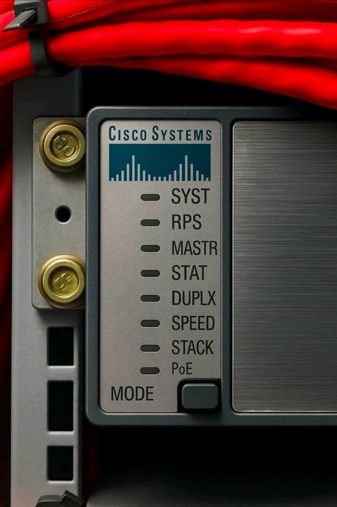
Cisco Catalyst switches include several front-panel LED indicators that allow network engineers to quickly understand the overall health of the switch, port connectivity, power status, stack operation, link speed, duplex mode, and PoE status.
These LEDs are especially useful during physical troubleshooting because they can provide valuable information before logging in to the switch through CLI, SSH, or a web interface.
In this article, we will review the most common Cisco Catalyst front-panel indicators, including SYST, RPS, MASTR, STAT, DUPLX, SPEED, STACK, and PoE, and explain how they can be used in real-world troubleshooting scenarios.
Note: LED behavior may vary depending on the Cisco Catalyst model and IOS/IOS XE version. For critical issues, always verify the LED meanings using the official Cisco Hardware Installation Guide for the specific switch model.
1. SYST – System Status
The SYST LED indicates the overall system status of the switch.
| LED Status | Meaning |
|---|---|
| Off | The switch is powered off or is not receiving power. |
| Green | The switch is powered on and operating normally. |
| Amber | A hardware or software fault may exist. |
Real-World Example
Consider an access-layer switch located on an office floor.
If the SYST LED is green, the switch is generally operating normally and users should be able to access the network.
If the LED turns amber, possible causes may include:
- Power supply failure
- Boot issue
- Hardware failure
- POST or system diagnostic failure
- IOS/IOS XE software issue
For example, if all users on a specific floor suddenly lose network connectivity, checking the SYST LED should be one of the first physical troubleshooting steps.
2. RPS – Redundant Power Supply
The RPS LED indicates the status of a connected Redundant Power Supply.
| LED Status | Meaning |
|---|---|
| Off | No RPS is connected. |
| Green | The RPS is connected and ready. |
| Blinking Green | The switch is operating using the redundant power source. |
| Amber | The RPS is connected but a fault exists. |
Real-World Example
In a data center, the primary power supply of a switch may fail unexpectedly.
If a Redundant Power Supply is connected and available, the switch can continue operating using backup power.
This prevents an immediate outage and allows connected servers and network devices to remain online.
An RPS indicator can therefore provide immediate information about whether the switch has experienced a primary power failure and has transitioned to a backup power source.
3. MASTR – Stack Master
When multiple Cisco Catalyst switches operate as a stack, one switch typically performs the active or master management role.
The MASTR LED helps identify which switch currently performs this role.
| LED Status | Meaning |
|---|---|
| Green | The switch is the master or active switch in the stack. |
| Off | The switch is not the master. |
Real-World Example
Imagine a core network consisting of four stacked switches.
Although these devices are physically separate, they can operate as a single logical switch from a management perspective.
One switch normally acts as the active or master switch and manages the overall stack.
If the active switch fails, another stack member may take over the management role depending on the platform and stack configuration.
This architecture improves:
- Availability
- Centralized management
- Operational simplicity
- Stack resiliency
4. STAT – Port Status
STAT mode is typically the default front-panel mode and shows the connectivity and activity status of switch ports.
| Port LED Status | Meaning |
|---|---|
| Solid Green | An active link is present. |
| Blinking Green | Traffic is being transmitted or received. |
| Amber | The port may be blocked, disabled, or experiencing a fault depending on the platform. |
| Off | No active link is detected. |
Example Scenarios
When a server NIC is connected to the switch, the port LED may appear as:
Solid Green
When the server starts transmitting or receiving traffic, the LED may begin:
Blinking Green
Another common example involves Spanning Tree Protocol.
If a redundant uplink is placed into a blocking or discarding state by STP to prevent a Layer 2 loop, the port LED may indicate an amber status depending on the switch model.
Why Is This Important?
Suppose a user reports:
“I cannot connect to the network.”
Before accessing the switch CLI, the network engineer can check the physical port LED.
If the LED is completely off, possible causes include:
- Ethernet cable disconnected
- Faulty cable
- User device powered off
- NIC disabled or faulty
- Switch port administratively disabled
- Physical layer negotiation failure
This can immediately narrow down the troubleshooting scope.
5. DUPLX – Duplex
Duplex determines whether a network interface can transmit and receive data simultaneously.
| LED Status | Meaning |
|---|---|
| Green | The port is operating in Full Duplex mode. |
| Off | The port may be operating in Half Duplex mode. |
Full Duplex
In Full Duplex mode, devices can send and receive data at the same time.
For example:
Access Switch <----> Core SwitchAn uplink between an access switch and a core switch should normally operate in Full Duplex mode.
This allows efficient bidirectional communication.
Half Duplex
In Half Duplex mode, transmission and reception cannot occur simultaneously.
This is mainly seen with legacy Ethernet devices.
For example, an older printer NIC may negotiate Half Duplex.
Possible symptoms include:
- Collisions
- Slow network performance
- Packet retransmissions
- Reduced throughput
In modern Ethernet environments, most connections are expected to operate in Full Duplex.
6. SPEED – Port Speed
SPEED mode allows the network engineer to determine the negotiated speed of an Ethernet port.
On some Catalyst models, the LED behavior may appear similar to the following:
| LED Status | Example Speed |
|---|---|
| Off | 10 Mbps |
| Green | 100 Mbps |
| Blinking Green | 1 Gbps |
Example
An older IP phone may establish a connection at:
100 Mbpswhile a modern laptop may negotiate:
1 GbpsTroubleshooting Importance
Suppose a user expects a 1 Gbps connection but the switch port is operating at only 100 Mbps.
Possible causes include:
- Faulty Ethernet cable
- Incorrect cable termination
- Unsupported cable category
- NIC limitations
- Speed or duplex configuration mismatch
- Intermediate device limitations
- IP phone pass-through port limitations
For example, a damaged Ethernet cable may prevent Gigabit Ethernet from negotiating successfully and cause the connection to fall back to 100 Mbps.
7. STACK
Supported Cisco Catalyst switches can be combined into a stack and managed as a single logical system.
The STACK LED helps identify stack-related status.
| LED Status | Meaning |
|---|---|
| Green | The switch is participating in a stack. |
| Blinking Green | Stack-related communication or activity may be occurring. |
| Off | The switch is not operating as part of a stack. |
Real-World Example
Consider an office environment with three access switches connected in a stack.
Although there are physically three different switches, administrators can often manage them as one logical system.
Benefits of stacking may include:
- Centralized configuration
- Simplified management
- Improved availability
- Easier uplink design
- Reduced number of management IP addresses
If there is a stack communication problem, the front-panel stack indicators can be one of the first troubleshooting points.
8. PoE – Power over Ethernet
Power over Ethernet, or PoE, allows both network data and electrical power to be delivered over the same Ethernet cable.
PoE is commonly used for:
- IP Phones
- Wireless Access Points
- IP Cameras
- IoT devices
- Network sensors
Depending on the Catalyst model, the PoE LED may indicate states similar to the following:
| LED Status | Meaning |
|---|---|
| Green | The port is providing PoE power. |
| Amber | The device requested PoE but power could not be provided, or a PoE fault exists. |
| Off | No PoE power is being delivered. |
Real-World Example
When an IP Phone is connected to a PoE-capable switch, the device can receive both data connectivity and electrical power through the same Ethernet cable.
The PoE indicator may therefore appear green.
However, Cisco switches have a limited total PoE power budget.
Consider the following example:
Switch PoE Budget : 740 W
PoE Power Used    : 735 W
New AP Requirement: 30 W
Only 5 W of power remains available.
If a newly connected Access Point requires 30 W, the switch cannot provide sufficient power.
The affected port may therefore display a PoE fault or denial indication.
When troubleshooting PoE problems, engineers should check not only the port configuration but also the total switch PoE power budget.
Mode Button
Cisco Catalyst switches commonly include a MODE button on the front panel.
The MODE button changes the type of information displayed by the port LEDs.
Common modes include:
STAT
Displays:
- Port link status
- Traffic activity
- Port condition
DUPLX
Displays the duplex mode of the ports.
For example:
- Full Duplex
- Half Duplex
SPEED
Displays the negotiated port speed.
Examples include:
- 10 Mbps
- 100 Mbps
- 1 Gbps
PoE
Displays the PoE status of supported ports.
This mode is especially useful when troubleshooting:
- IP Phones
- Wireless Access Points
- IP Cameras
Real-World Troubleshooting Scenario
Suppose a user reports:
“My computer cannot connect to the network.”
A network engineer could perform the following checks.
Step 1 – Check the SYST LED
First, verify the overall switch condition.
SYST = GreenThe switch appears to be operating normally.
Step 2 – Check the User Port
Assume the user’s device is connected to:
GigabitEthernet1/0/10The port LED shows:
LED = OffThis indicates that no physical link has been established.
Possible causes include:
- Ethernet cable disconnected
- Faulty cable
- User device powered off
- Disabled NIC
- Switch port administratively shut down
Step 3 – Reconnect or Replace the Cable
After reconnecting the cable, the LED changes to:
Solid GreenThis indicates that a physical link has been established.
When traffic begins flowing, the LED may change to:
Blinking GreenStep 4 – Check Port Speed
Use the MODE button to select SPEED mode.
The expected connection is:
1 GbpsIf the port is operating at only:
100 Mbpsthe engineer should investigate:
- Cable quality
- Cable termination
- NIC capabilities
- Intermediate devices
- Port speed configuration
Step 5 – Check Duplex
The expected connection should normally be:
1 Gbps / Full DuplexIf a duplex mismatch is present, network performance may be significantly affected.
Quick LED Reference Table
| LED | Purpose |
|---|---|
| SYST | Overall switch system status |
| RPS | Redundant power supply status |
| MASTR | Stack master or active switch |
| STAT | Port connectivity and traffic |
| DUPLX | Duplex mode |
| SPEED | Port link speed |
| STACK | Stack membership and status |
| PoE | Power over Ethernet status |
Using LEDs with the OSI Troubleshooting Model
One of the main advantages of front-panel LEDs is that they allow troubleshooting to begin at OSI Layer 1 – Physical Layer.
A structured troubleshooting flow could look like this:
User reports connectivity problem
             |
             v
Check SYST LED
             |
             v
Check Port STAT
             |
             v
Check Speed / Duplex
             |
             v
Check PoE
             |
             v
Check Cable / NIC
             |
             v
Check Switch Port Configuration
             |
             v
Check VLAN
             |
             v
Check Spanning Tree
             |
             v
Check IP / DHCP
             |
             v
Check Routing
This method helps engineers narrow down the issue before moving to more complex Layer 2 or Layer 3 troubleshooting.
Cisco Catalyst front-panel LEDs may appear to be simple status lights, but they provide valuable information during network troubleshooting.
By performing a quick physical inspection, a network engineer can determine whether:
- The switch is operational
- A port has an active physical connection
- Traffic is flowing
- The correct link speed has been negotiated
- The port is operating in the expected duplex mode
- PoE power is being delivered
- The switch is participating in a stack
- A redundant power source is active
For field engineers, data center teams, and network administrators, checking front-panel LEDs should therefore be one of the first steps in troubleshooting a connectivity issue.
However, LED colors and blinking behavior can vary between Cisco Catalyst platforms. Always verify the exact LED behavior using the official Cisco documentation for the specific switch model.
